Understanding CNC Machines: Axes, Coordinates and G-code (Basics)
When people first encounter CNC machines, they often hear terms like “3-axis,” “5-axis,” or see snippets of mysterious G-code. This article breaks down what those terms mean, why the number of axes matters, and how software ties everything together. We’ll also look at laser engravers, which share many principles with CNC machining.
CNC Basics
CNC stands for Computer Numerical Control. At its core, a CNC machine translates a digital design into precise tool movements. Instead of manually operating a milling machine or lathe, the CNC controller interprets code and drives motors to cut, drill, or engrave material.
CNC machines are built on the Cartesian coordinate system:
- X-axis → left–right
- Y-axis → front–back
- Z-axis → up–down
With just these three, you already have a versatile machine. But higher-end machines add rotational axes that dramatically expand capability.
3 vs. 4 vs. 5 Axes
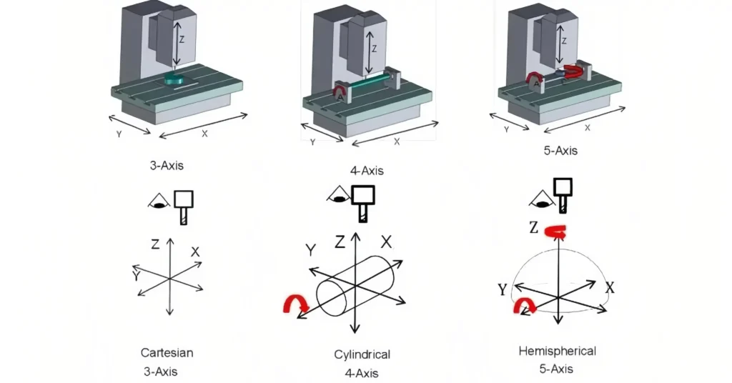
- 3-axis: The cutting tool moves along X, Y, and Z. Most desktop routers and entry-level mills fall into this category. Great for flat surfaces, pockets, and simple 3D contours.
- 4-axis: Adds rotation around one axis (usually called A). Imagine clamping a cylinder and rotating it while cutting — this makes complex spirals, gears, or relief carvings possible.
- 5-axis: Two rotational axes (commonly A and B). The tool can tilt and rotate relative to the workpiece, machining from virtually any direction. This reduces the need to reposition parts manually and enables manufacturing of complex aerospace or automotive components.
G-code: The Language of CNC
Every CNC machine executes a sequence of instructions known as G-code. Each line tells the machine what motion to perform, how fast to move, or how to control the spindle.
G-code Documentation: https://marlinfw.org/meta/gcode